One of the objectives of LoRa Smart system communication is the efficient collection of data required for the tracking, control, and analysis of consumption on the administration's water distribution network in provinces and districts (including villages).
With the implementation of smart system communication, it is aimed to acquire the following qualities;
- Reducing the non-revenue water rate by minimizing leakages and losses,
- Increasing customer service variety, quality, and satisfaction,
- Eliminating reading and billing problems,
- Reducing meter reading costs,
- Managing the water distribution network better.
By adding a LoRa RF Meter Module to mechanical water meters suitable for remote reading in provinces and districts (including villages and agricultural areas) within the responsibility areas of water administrations, the collection of data from the meter module and its transmission to the center is ensured.
For remote reading, installation, periodic controls, and service operations; the LoRa RF Meter Module, Gateway, Network Server and Module Service/Installation Software, hand terminal and/or local reading device are provided within the scope of LoRa Smart System Communication.
DESCRIPTION OF THE SYSTEM
The system basically consists of; the RF Meter Module that receives consumption and alarm data from the meters, stores them, and sends the requested ones; Gateways that collect the data sent from the module and transfer it to the system center; and the network server that collects the data from all Gateways and transmits it to the Smart Meter System software.
The lower end of the system begins with the module, mounted on mechanical water meters ready for remote reading, converting the rotation of the metal pulse target on the mechanical meter into digital data using the inductive sensing method. With this sensing, many operations such as index advancing, reverse-forward flow direction detection, flow rate calculation, and removal detection are performed. Data generated as a result of the operations are recorded into the internal memory with date-time stamps by the module processor. Alarms resulting from these operations recorded in the internal memory are sent to the system the moment they occur, and the Administration can parametrically change the alarm types for which it wants to obtain instant information through the software. The module broadcasts the desired data packets at programmed (parametrically adjustable from the center) periods (daily, weekly, monthly, etc.) via the communication integrated circuit with LPWAN technology. These broadcasts are continuously listened to and verified by Gateways within the reach of the RF signal. The LPWAN technology to be used is capable of broadcasting from a distance of at least 10 km in open areas. Gateways check the intact data packets reaching them and send them to the Network Server via GPRS and/or Ethernet. The network server checks the incoming data and transmits the appropriate data packet to the application server. The encryption of the data packet arriving at the application server is decrypted here and recorded in the database.
The communication network defines the communication structure from the RF Meter Modules to the central system. The RF communication system will be established using a Fixed Network, star network structure; Walk-by/Drive-by structures will not be accepted, and repeaters or relays will not be used. All data transmissions within the communication network will be encrypted with AES 128 or XTEA 256-bit algorithms and protected against external interference. Encryption keys will be changeable via local and remote communication.
During communication between all system devices within the communication network, the protection of information, ensuring its integrity, and its accessibility and reachability are ensured. Meter data to be carried over the system is encrypted with the AES 128 or XTEA 256-bit encryption standard and can only be decrypted by the central software at the final stage of communication.
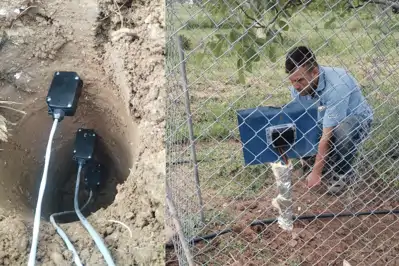
LoRa RF METER MODULE
The LoRa RF Meter Module is mounted on the remote-reading-ready mechanical water meters that the Administration is using in the field. The RF Meter Module records measurement data by receiving pulses from the mechanical water meter. The received measurement data is sent via the communication system. If a module installed on a subscriber's meter is removed for any reason, the removed module can be installed on another subscriber's meter and can fully perform its function on the new meter. RF Meter Modules can keep retrospective log information in their internal memory for operations such as installation, service, maintenance, control, testing, battery usage, etc., and allow past data to be viewed if needed.
Index Sensing from Mechanical Meter
In order to perform the index sensing process from the mechanical water meter without loss and reliably, the pulse sensing process is performed inductively. The mechanical water meters that the Administration is using in the field and wishes to include in the communication system have the necessary hardware for pulse sensing with an inductive sensor.
Mechanical meters wind their index backward during reverse flows passing through them. The pulse sensing hardware of the RF Meter Module must be in a structure to detect reverse flow in case of any reverse flow in the meter for any reason.
Verifying that the RF Meter Module is receiving data securely on the mechanical meter is of great importance for determining the values based on billing. Therefore, in the pulse sensing hardware, it can be detected that the measurement is affected due to objects that can be placed between the mechanical meter and the sensing hardware.
Index sensing from the mechanical meter is carried out with a 3-coil inductive sensing structure, and the structure and sequence of the incoming values are analyzed by the RF Meter Module.
The module can be installed and removed without removing the meter from the plumbing and without damaging the calibration seals of the meter. The module must be protected with a sealing device and can be mounted directly on the register part of the meter. Modules must be fully compatible with existing (DN20) meters; no reading errors or intervention alarms caused by not fitting the meter due to ordinary vibration that may occur for various reasons occur. It will be in a technological structure that will not produce false signals by being affected by vibration that will occur in the plumbing.
Recording Measurement Data
The RF Meter Module calculates and records the index information it receives from the mechanical water meter in the formats required for system analysis.
For the water management analyses needed by the Administration, the following records must be kept by the RF Meter Module and can be sent to the network server.
Forward Index: The amount of water flowing through the mechanical meter in the forward direction (consumption direction).
Reverse Index: The amount of water flowing through the mechanical meter in the reverse direction (opposite to the consumption direction).
Total Index: The net total formed by the difference between the Forward and Reverse Index and seen on the mechanical meter.
Consumption Profile Records
The RF Meter Module keeps time-stamped consumption curves so that historical records can be obtained and the subscriber's water consumption curve can be determined. The minimum number of records and information to be kept, which are necessary to ensure reliability in historical studies and continuous analyses, are as follows.
Time-Interval Consumption Curve Record: In a structure that can be adjusted in 15-min, 30-min, and 60-min periods, it can keep status records along with the Forward and Reverse consumption amounts passing through the meter within the period. Considering a 15-minute period, 90 days of retrospective data, i.e., a total of 8640 records, can be stored in the module, and this information can be read via local communication.
Daily Consumption Record: It can store the total consumption formed as of the end of the day along with status information and the reverse consumption information formed during that day in its memory. Daily consumption records can be stored for 1 (one) year retrospectively, i.e., 365 records.
Monthly Consumption Record: It can store the total consumption formed as of the end of the month along with status information and the reverse consumption information formed during that month in its memory. Monthly consumption records can be stored for 10 (ten) years retrospectively, i.e., 120 records.
Flow Curve Records
In order to monitor the wear and aging status of the mechanical meter used, and also to check whether the meter suitable for the subscriber type has been selected and to perform related analyses, the RF Meter Module records flow curves in at least 6 (six) different flow ranges. The limit values that will determine the flow ranges are programmable according to the mechanical water meter on which the module will be installed.
Flow measurements must be made with 1% accuracy, and operating times in flow ranges are recorded with second resolution.
Flow records must be updated instantly, and at the end of each month, the consumption characteristic in the flow ranges belonging to that month must be stored as past month information; the current record starts by being reset for the new month. Two years of meter usage characteristics can be read from the module with at least 24 retrospective records.
In instant readings, the current record can be read, including the flow curves recorded from the beginning of the month until the reading time.
Very Low, Excessive, and Constant Consumption
The RF Meter Module can detect Very Low and Excessive Consumption situations to determine whether the mechanical meter is used in accordance with its characteristics. It detects consumptions lower than the Qmin value of the mechanical meter in a programmable duration and consumptions higher than the Qmax value in a programmable duration and records them as alarms. In this way, consumption amounts that fall outside the sensitivity of the meter will be determined. Additionally, to minimize the loss water rate, it can record this situation as an alarm when a constant consumption is seen for a programmable duration.
Reverse Flow Detection
The RF Meter Module can detect if there is a flow in the reverse direction from the meter for any reason. This situation is recorded as an alarm along with the flow amount and duration. The reverse flow duration is recorded with at least second resolution for accurate analysis.
Reverse Installation of the Meter
The situation where the mechanical water meter is installed reverse to the consumption direction due to installation and/or intervention to the meter is detected by the RF Meter Module. Whether the meter is installed reverse to the consumption direction is decided by looking at the content of past daily records for a programmable number of times when reverse and/or forward consumptions occur. In order to prevent illegal usage by users, reverse flow status detection must be done instantly, and the amount of water flowing in the reverse direction is recorded in the Reverse Index.
Module Removal Detection
The RF Meter Module will be an integral part of the mechanical water meter, and data based on billing will be provided from the RF Meter Module. Therefore, removing the module is equivalent to removing the meter, and an alarm is generated in the central software when the module is removed.
To ensure the reliability of removal detection, this situation can be detected by the module using at least two different methods. Results obtained with both methods must be verified with each other and subsequently recorded. When removal occurs, an alarm record is created with the start date and time for this situation, and when it is reinstalled, the alarm record is concluded with the end date and time.
Seal Removal Detection
RF Meter modules will be in a structure to be mounted on cold water meters suitable for remote reading with stainless screws. An intervention to the screw on the module is an attempt to remove the RF meter module. Since the removal of the seal placed on the screw and having a magnet at the bottom is qualified as an attempt to remove the module, a seal removal detection alarm is generated in the system.
Magnetic Magnet Detection
The RF Meter Module protects against magnetic magnet effects. An external magnetic magnet approach situation can be detected by the RF Meter Module and recorded as an alarm. The magnetic intervention value detection threshold level can be programmed in milli-Tesla units.
Communication Features
Remote Communication
The Administration will read the meters remotely via the RF Meter Module to collect meter data and create consumption analyses based on this data. With the RF technology reading system to be used, the Administration aims to reduce the amount of non-revenue water and increase water network management efficiency. Therefore, the RF technology to be used operates in the 868 MHz unlicensed frequency band in accordance with the Regulation on Short Range Radio (SRD) Devices of the Information and Communication Technologies Authority (BTK). In addition, RF Meter Modules comply with the duty cycle times and output powers within the scope of the same regulation. The maximum output power is at most 25mW.
The RF Meter Module will send meter data to the central system at specified periods. The data to be sent can be adjusted parametrically by system users and is in a structure to be determined according to modulation levels; additionally, it can communicate bi-directionally in a structure that will check if there is a work order coming from the center.
Connection periods can be configured by the administration according to the region where the meter is located, the type of subscriber using it, and/or the type of analysis to be performed. Connection time should be determinable with second resolution and can be set as hourly, daily, weekly, or monthly. Different connection times can be set for different data packets.
Outside of connection times, the RF feature is in the off state to avoid battery consumption and detection of signals coming from outside.
The communication protocol to be used has an open and testable communication protocol determined by international standards. In order to transmit data to the central software and increase signal quality, modulation level and communication speed optimization are in a structure that can be adjusted by the network server software. RF Meter Modules support communication speeds from 300bd to 9600bd.
Necessary security measures for the entire communication system to be established can be provided with encryption methods. In the RF communication to be made by the module, data is encrypted with the AES 128 algorithm, and passwords can only be decrypted by the network server software.
Local Communication
RF Meter Modules have wireless, high-speed local communication technology independent of the remote communication channel so that the administration can perform service operations requiring large data transfers, such as installation, service, maintenance, control, testing, reading detailed retrospective log information, and updating module meter software, with authorized personnel uninterruptedly. The technology to be used at short distances is capable of performing a 128 kB update of the software inside the module in at most 35 seconds, excluding control.
Local communication will only be activated by authorized personnel during service, maintenance, local reading, or installation operations and will be turned off at other times to reduce battery consumption and prevent possible interventions to the module. Authorization access can be defined at different levels.
Time Clock
The RF Meter Module includes a real-time clock to execute time-based operations. The real-time clock supports dates up to 31.12.2100, and the clock deviation is at most 0.5 seconds in 1 day. Time clock deviation complies with the international IEC 62052-21 standard.
Real-time clock synchronization can be done remotely and with the module service installation software. If the difference between the RF Meter Module's clock and the clock to be synchronized is large in case of clock synchronization, the time synchronization process is not allowed.
In adjustments that cannot be made with time synchronization, clock adjustment can be made remotely and locally only by authorized personnel. Changes made to the real-time clock are recorded within the RF Meter Module. The real-time clock must support daylight saving time and leap year applications and can be configured as active or passive.
Power Supply
The power supply of the RF Meter Module is provided by an internal battery inside it. It gives a battery alarm to the system at least 6 (±2) months before the battery runs out. The RF Meter Module provides the energy need for all operations it will perform from the battery inside it. The energy need of the RF Meter module will be met from batteries with lithium technology, whose production date belongs to the year it was delivered to the Administration (except those delivered in the first six months of the year).
The battery inside the RF Meter Module can be used for at least 10 years to receive data after installation and commissioning.
Mechanical Features
The RF Meter Module has at least IP68 protection class to show resistance to harsh working environments and not be affected by elements coming from the external environment such as water and dust. As a body material, it has a claw structure that will not be affected by the sun and is resistant to disassembly and assembly. The RF Meter Module can operate without performance loss in the temperature range from -10°C to +50°C and at 95% humidity. In addition, it can store its data from -25°C to +70°C.
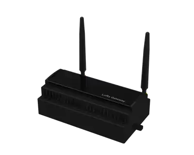
Gateway
The remote communication system is provided by Gateways to be placed at dominant points (high areas, points with wide coverage). RF Meter Modules communicate directly with Gateways and transmit their data to the central system.
The RF technology to be found in gateways operates in the 868 MHz unlicensed frequency band in accordance with the Regulation on Short Range Radio (SRD) Devices of the Information and Communication Technologies Authority (BTK).
The Gateway can communicate bi-directionally with the RF Meter Module. It can transmit information from the RF Meter Module to the center and information from the center to the RF Meter Module.
In order to calculate the signal quality between the Meter Module and the Gateway it reaches and to increase the system performance accordingly, the Gateway measures the strength of the incoming signals and transmits this information to the central system.
Gateways are capable of bi-directional communication with the RF Meter Module by directing the data sent from the RF Meter Module to the central system. It will transmit information from the RF Meter Module to the center and information from the center to the RF Meter Module and will not keep meter data in its own memory. Communication between the central system and the Gateway can be provided by GPRS and/or Ethernet. The Gateway supports IEEE 802.3y Ethernet and GPRS/EDGE (850/900/1800/1900MHz) bands. For GPRS communication, simcards defined within the Administration's APN will be used.
Gateways have a high-performance operating system capable of managing communication with high numbers of endpoints. This operating system can preferably be Linux or Windows Embedded. The Gateway software to run within this operating system is in an updatable structure. Configuration settings within the Gateway are in a structure that can be programmed via remote and local communication. To support the future expansion and development of the system, Gateways are equipped with advanced hardware features, including at least a 256 MHz processor, at least 128 MB Ram, and at least 128 MB Flash Memory. Additionally, a real-time clock and watchdog timer are used to ensure the operational reliability of the Gateways. In case of power interruptions, the real-time clock will continue to operate with the internal battery and will shut itself down safely. If the Gateway does not have an internal battery, it will receive the real-time information from the system after the interruption and synchronize the time information.
In order to evaluate the environmental conditions where installation is made and to take precautions against possible effects it will be exposed to, Gateways have a temperature sensor and at least one control input.
All communications that the Gateways will make with the RF Meter Module and the central system will be encrypted. In addition, necessary precautions will be taken for network security.