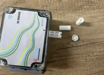
1. To access the inside of the box and make connections, you need to open the metal clips circled in red and open the clip by carefully pulling the arms of the clip outwards or lifting them upwards, but let's be careful while opening because in this way the clip will release the cover of the box and access to the device inside will be provided. After opening the clips, you can slowly lift the cover of the box. Thus, you will have access to the internal components and connection points of the device
2. When wiring, take care to pass the cables correctly into the cable slots shown in the red circle above. Identify the relevant connection points and cable slots. These points may usually be numbered or marked on the device. Place the cables correctly into the cable slots and connect them firmly. It is important that the connections are solid and the cable is seated properly
Wiring Diagram
How to Install the Central Station? Follow the steps below to perform the numbered processes above in order: 1.12V Power Supply Input: Connect the red cable to the (+) positive pole, and the black cable to the (-) negative pole. 2.M1+ M1- Valve Sensor Input: Make sure you connect the cables correctly. 3.A1+ A1- Pressure Sensor Input: Connect the red cable to the (+) positive pole, and the black cable to the (-) negative pole. 4.I1+ I1- Pulse (Water Meter) Sensor Input: Connect the red cable to the (+) positive pole, and the black cable to the (-) negative pole. 5.C1 C2 C3 C4 Pump Sensor Input: Connect the red cable to the (+) positive pole, and the black cable to the (-) negative pole
SIGNAL COLORS AND THEIR MEANINGS
1. RF Light: Red light indicates the device's data exchange. It should flash rapidly while the operation is being performed.
2. GSM Light: When the GSM card is inserted, this light should be green.
3. Connect (Connection Light): Orange light indicates the status of the device's internet connection. If the light is on, there is an internet connection; if it is off, there is no internet connection.
4. Green Glowing Light: This light indicates that the device is working. If it is green, it means the device is working correctly.
5. Power Light: This light shows that energy is being supplied to the device. If the power light is not on, energy may not be supplied to the device. Check the power source and make sure you have connected it correctly.
SIM CARD
1.GSM (SIM Card) Slot: Use this slot to insert the device's SIM card
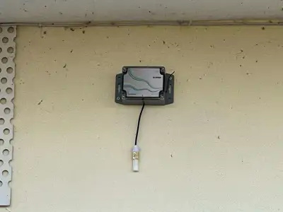
Antenna Inputs
1. GSM Antenna Input: Connect the GSM antenna here so that the device can receive the GSM signal. 2. RF: Wi-Fi Antenna Input: Connect the Wi-Fi antenna here so that the device can receive the Wi-Fi signal.